[ Class Overview ] [ CGA Screen ] [ Keyboard ]
Character and Key Codes
For the interaction with the PC keyboard, several different codes are relevant and will be discussed in the following.ASCII Code and CP 437
The "American Standard Code for Information Interchange" is the classic character-encoding standard for representing letters, digits and special characters as 7-bit numbers between 0 and 127. The original IBM PC extended this encoding to 8 bits with a standard called "code page 437", introducing umlauts, accented characters, greek letters, and line-drawing symbols. A small excerpt from the ASCII (and CP 437, a superset of ASCII) character table:
| Character | ASCII code |
|---|---|
| ( | 40 |
| 0 | 48 |
| 1 | 49 |
| 2 | 50 |
| A | 65 |
| B | 66 |
| a | 97 |
Characters and strings are classically stored in ASCII encoding.
Scancode
The scan code is used to assign unique numbers to the keys on the PC keyboard. This also makes it possible to identify keys that do not correspond to printable characters, such as e.g. the cursor keys. Scancodes do not distinguish between uppercase and lowercase letters, since both are typed in with the same key.
| Key | Scancode |
|---|---|
| A | 30 |
| S | 31 |
| D | 32 |
| Cursor up | 72 |
| Cursor down | 80 |
Throughout the PC's history, different keyboards with a different number and meaning of keys were built. Especially the "function" and "special" keys can have different scan codes on different models. Since PC keyboards usually have only a maximum or a little more than 100 keys, 7 bits suffice to represent the scan code.
Make and Break Codes
Programs must be able to determine not only which of the "normal" keys
have been pressed, but also whether the Shift key, the Control key or the ALT
key were held down at the same time.
Therefore, instead of a simple scan code, the keyboard sends one or more
so-called make codes for each press and one or more break codes
for each release of a key.
If a key is held down for longer than a certain period of time, the make code(s)
are repeated.
For most keys, the make code corresponds to the scan code, and the break code
corresponds to the scan code with the most-significant bit set (i.e., offset
+128).
However, for historical reasons, some keys generate multiple make and break
codes even when pressed and released once.
The keyboard driver (starting with task #3: Keyboard::prologue())
must map make and break codes of the pressed keys to ASCII codes the application
can work with.
Note: Since the interpretation of the make and break codes is rather
tedious, boring and not very instructive, we have taken the decoding off your
hands in the Keyboard_Controller template code.
However, it may be that our implementation does not correctly recognize all
characters on your keyboard, especially German umlauts.
In this case, you will either have to live with a few wrong characters or adjust
the decoding tables accordingly.
Key-press Sequence
When a key is pressed on a PC keyboard, two crossing lines of the scan matrix are connected within the keyboard, closing an electric circuit. The keyboard processor (classically an Intel 8048) determines the position of the pressed key and from this the scan code. This code is sent to the keyboard controller (Intel 8042 for PC/XT) on the PC mainboard via a serial interface.
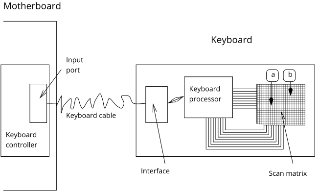
This keyboard controller communicates with the keyboard via an input port and an
output port (for commands to the keyboard).
The controller has registers that can be read and written to via the system bus
using in and out instructions.
| Port | read (R), write (W) | Register | Meaning |
|---|---|---|---|
| 0x60 | R | Output buffer | Make/break codes from the keyboard |
| 0x60 | W | Input buffer | Commands for the keyboard (e.g. set LEDs) |
| 0x64 | W | Control register | Commands for the keyboard controller (e.g. reboot) |
| 0x64 | R | Status register | Keyboard-controller state (e.g. output buffer full?) |
Whenever the keyboard controller writes a byte to its output buffer, it signals this by setting an interrupt request. The processor must react to this by reading the arrived byte from the output buffer. The outb bit 0 in the status register then transitions to 0, indicating that the output buffer is empty again. Only now new characters can be accepted from the keyboard. If the keyboard is used in polling mode, the outb bit can be used to check whether there is actually a character in the output buffer of the keyboard controller. In the opposite direction, it is always necessary to wait until the input buffer of the keyboard controller is empty (inpb bit 1 cleared) before a new character is written.
On PS/2 PCs, the mouse is also connected to the keyboard controller. This means that codes from both the keyboard and the mouse end up in the output buffer. To distinguish the source of the byte, bit 5 (auxb) is available in the status register (1 = mouse, 0 = keyboard).
| Bit | Mask | Name | Meaning |
|---|---|---|---|
| 0 | 0x01 | outb | Set to 1 when a character is ready to be read from the output buffer of the keyboard controller |
| 1 | 0x02 | inpb | Set to 1 as long as the keyboard controller has not yet fetched a character written by the CPU |
| 5 | 0x20 | auxb | Source of the value in the output buffer (0 = keyboard, 1 = mouse) |
Configuring the Keyboard
The keyboard can be configured by sending command codes via the input buffer. A total of about 20 commands are supported, but we only use two of them: One to drive the LEDs and one to set the repetition rate and delay. Both expect an additional data byte after the command byte.
Before sending a byte to the keyboard, you should make sure that the input
buffer is empty (status register, inpb), then write the byte (command
code or user data) to the data port.
Then you should wait for a response from the keyboard controller (outb)
and check whether the output buffer contains the acknowledgment code
0xfa (ACK).
Formally, only then the next byte may be sent.
Note that after each byte an ACK is returned – i.e. one after sending the
command code, and another one after sending the user data.
Note that while a clean solution would wait for an ACK after every command code, it is non-trivial to achieve a fully standard-conforming implementation. Correctly waiting for an ACK is difficult, as it may be interwoven with or squashed by subsequent key presses. Therefore it is okay to simply ignore the acknowledgment byte.
| Command code | Name | Description |
|---|---|---|
0xed | set_led | Configure the keyboard LEDs. After the command code, an additional data byte must be sent to the keyboard; its structure is described below in a separate table. |
0xf3 | set_speed | Set repeat rate and delay according to a data byte following the command byte; its structure is described below in a separate table. |
The following table shows the structure of the data byte of set_led for setting the keyboard LEDs. MSB means most significant bit (i.e. 0x80 in hexadecimal notation), LSB least significant bit (i.e. 0x01).
| MSB | LSB | Always 0 | Always 0 | Always 0 | Always 0 | Always 0 | Caps Lock | Num Lock | Scroll Lock |
|---|
The following two tables describe the data byte of set_speed. The repetition rate is specified by bits 0–4, the delay by bits 5 and 6.
| Bits 0–4 (hex) | Repeat rate (characters per second) |
|---|---|
0x00 | 30 |
0x02 | 25 |
0x04 | 20 |
0x08 | 15 |
0x0c | 10 |
0x10 | 7 |
0x14 | 5 |
| Bits 5 and 6 (hex) | Delay (in seconds) |
|---|---|
0x00 | 0.25 |
0x01 | 0.5 |
0x02 | 0.75 |
0x03 | 1.0 |
Further Information and References
- Messmer, Hans Peter: PC-Hardwarebuch – Aufbau, Funktionsweise, Programmierung. Addison-Wesley 1994
- The AT keyboard controller